The Electromagnetic Calorimeter for BelleII experiment (ECL) will reuse the central part (barrel) of the Belle detector while a new calorimeter is forseen in the forward region. The Belle electromagnetic calorimeter consists of 8736 CsI(Tl) crystals with typical dimension of 6×6×30 cm3. The length corresponds to about 16 X0. Figure 1 shows the schematic view of the calorimeter and a crystal equipped with photodetectors.
The main purpose of the electromagnetic calorimeter is to detect photons and π0's from B meson decays. Energy of such photons ranges from few MeV to few GeV. Energy resolution is very important in order to separate signal and background events only with mass distribution. To separate two photons from high momentum π0, fine granularity is required. Hermeticity is also very important to study final states with neutrinos. The calorimeter has pointing geometry and covers polar angle from 12° to 155°. The scintillation light of the CsI(Tl) crystal has λ = 560 nm with rather slow decay constant of 1.3 μsec but abundant light output of about 50000 p.e./MeV. The light is read out by two independent sets of silicon PIN photodiodes (Hamamatsu S2744-08) with sensitive area of 10×20 mm2 connected to charge sensitive preamplifier. Two signals from preamplifiers are first added and then processed with two shapers with 0.2(fast) and 1μsec(slow) shaping times. The fast signals are used to generate triggers while the slow ones are sent to a LeCroy MQT300A charge-to-time converter. The time encoded energy information is then recorded with LeCroy 1877S Fastbus TDC. The readout system consists of about 100 TDC boards in five crates read out by three VME systems. It takes about 30μsec to read out one physics event. The trigger rate is about 300 Hz with instantaneous luminosity of 1034 cm−2 sec−1, which corresponds to about 1% readout deadtime. Although the signal is recorded with TDC, only the energy is saved. No event timing information is available.
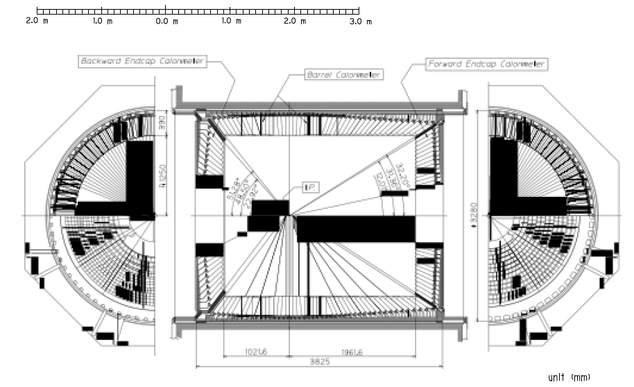
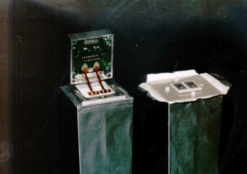
Figure 1. (Left) The Belle Electromagnetic Calorimeter. (Right) A counter.
In the BelleII experiment the trigger rate will be 30 kHz and the background 10 times higher than in Belle. Radiation damage is an issue for high luminosity collider experiments and the calorimeter will also be affected. To cope with such situation waveform sampling together with pipelined readout will be introduced. The former enables us to use timing information to discriminate off-timing hits while the latter can eliminate effectively readout deadtime. This will be implemented replacing the readout electronics with a new one. Figure2 shows the schematic diagram of the new readout system.
Heart of the system is a Shaper Digitizer board which receives preamplified signals from 16 crystals. Two preamplifier signals from one crystal are summed and processed by a shaper with time constant of 0.5μs. Reducing shaping time further is not efficient as the time constant of scintillation is 1.3μs. The shaped signal is digitized by 18 bit ADC with 1.8 MHz sampling rate and sent to a pipeline buffer in FPGA which is 512(290μs) deep. Once a trigger is issued, waveform fitting is performed in FPGA using 16 samples to extract timing and amplitude. According to simulation studies a reduction of a factor of seven in the cluster fake rate is expected with the upgraded readout system.
To readout all 8736 crystals, a total of 576 Shaper Digitizer boards are placed in 52 VME crates. In each VME crate a Collector board will be installed. The Collector board receives trigger signals and distribute them to the Shaper Digitizer boards in the crate, receives also fitted timing and amplitude and sends them to backend DAQ system via optical link. Introducing Collector board greatly reduces the number of cables from the detector to electronics hut. The Collector board can also supply calibration signals. Figure 2 shows a schematic diagram of the new DAQ system.
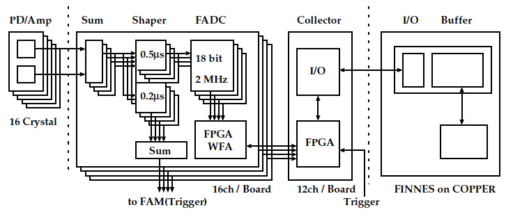
Figure 2 Schematic view of the readout system.
Status of the detector
New Shaper Digitizer boards and collector modules have been produced and tested. Figure 3 shows digitizer board (left) and collector board (right).
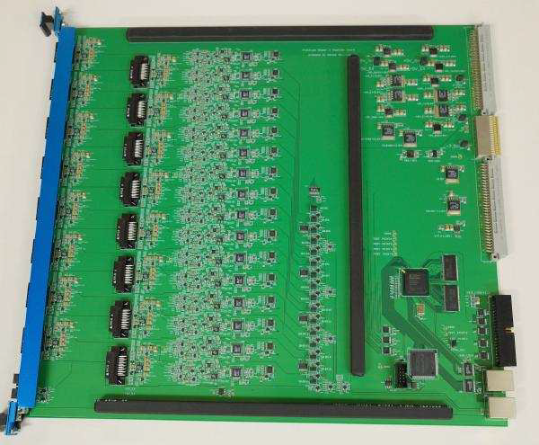
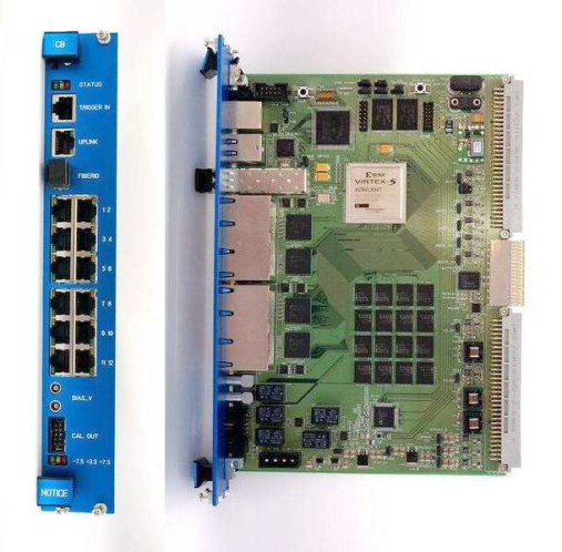
Figure 3. (Left) Shaper Digitizer prototype. (Right) Collector prototype.
Currently, R&D studies with prototype VME shaper digitizer and collector boards, produced recently, are ongoing. The plan is to produce all 432 barrel boards and all 52 collector boards by mid 2014.
Due to the higher background and very high occupancy, in the forward region the calorimeter will be replaced with a pure CsI crystal one. The decay time of 30ns makes this crystal suitable to operate at a luminosity of 8x1035 cm-2s-1. The baseline option for the readout of pure CsI crystals is photopentodes, an R&D is ongoing to study the possibility of using APD's. Avalanche Photodiodes have the advantage of being smaller and two of them could be installed in a crystal allowing a redundancy in the readout. No change in the mechanics will be necessary and they are not sensitive to the magnetic field. On the other hand they are sensitive to temperature variation and they have a gain much smaller than phototubes.
The Italian collaboration involved in the ECL subdetector for the BelleII experiment is responsible of the R&D effort for the APD readout. Five groups from INFN (Istituto Nazionale di Fisica Nucleare) are contributing: ENEA-Casaccia (associated at Rome1 Section of INFN), LNF (Laboratori Nazionali di Frascati), Naples, Perugia and Rome3.
ENEA-Casaccia: characterization of the crystals in terms of Light Yield, Transmittance and Uniformity. Facilities for irradiation with photons and neutrons are available at the ENEA-Casaccia laboratories and then radiation hardness studies will be performed on crystals and on photodetectors.
LNF and Perugia: the two groups are collaborating to study the possibility of performing the readout of pure CsI crystals with APD's. Test of different types of APD's in terms of noise level, signal to noise ratio and stability in time. Evaluation of the performance of the crystal for different APD's, UV-enhanced, Large Area APD, UV-enhanced with very small capacitance to reduce the noise.
Naples and Rome3: development and test of the Front End electronics for the different type of photodetectors. The two groups are also developing a system remote control for the monitoring of temperatures, applied voltages and gains.