
Working Group
- Stefano Mastroianni
- Walid Idrissi Ibnsalih
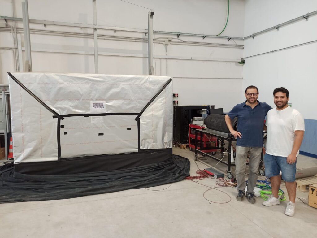
Once all the 18 DOMs are electrically and optically connected to the VEOC and accordingly to the BM, the DU is in principle in its final shape and ready for the installation. However, before continuing with the last procedure, that consists of rolling the DU on the LOM (process 4), the string needs to be tested and calibrated in a dedicated dark box to validate the detector string under real operating conditions before the deployment.
In fact, several tests and checks are performed to validate the proper functioning of the optics, acoustic receivers, connectivity and data readout system of each DOM. Also for the BM, communication and data acquisition are verified together with the correct operation of the acoustic emitter (beacon) and receiver (hydrophone) attached to it. Here, a brief description of the procedure for qualification and certification of all the components (from single PMT to the entire DU) during the so called process 3, is provided.
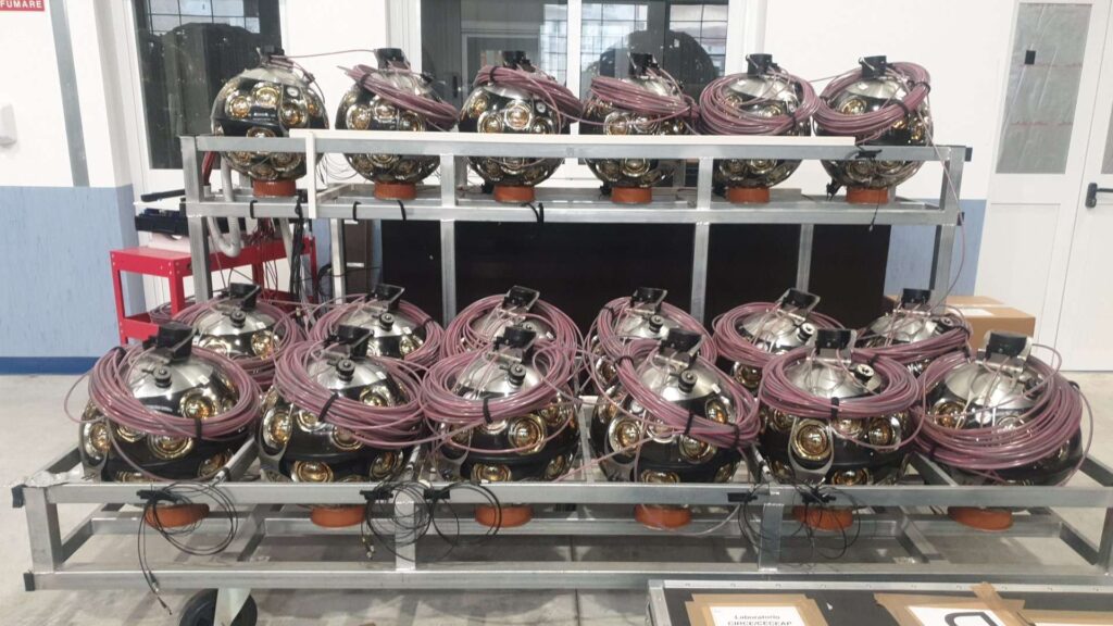
The DOMs are firtsly arranged on a support frame and placed inside the dark box to shield the PMTs from ambient light. Then, after a few days of darkening the process 3 can start. However, during this time, some preliminary operations (both hardware and software) regarding the test station configuration (i.e. connection of auxiliary devices and network setup) and the detector definition through the interaction with the central database to integrate a list of DOM components and processes for trigger and data acquisition.
A test station computing facility based on the same architecture of the experiment’s shore stations for physics data taking, implements all the functions of detector control, data acquisition, run control, data flow and data logger, and is used for testing the detector operation and data readout of each DOM.
At the first DU power on, the communication protocol and the clock synchronization can be verified for all the data acquisition nodes, namely BM and DOMs. Then, the electrical power measurements are performed according to a well defined sequence of operating conditions (BM with hydrophone/beacon respectively in on and running mode and DOMs going through off/on/running status).
The first runs of data taking performed with high voltage (HV) vendor allow the PMT checking: ToT distributions are used to exclude PMTs with extreme low and high counting rates. In order to optimize the PMT gain, the HV tuning can be performed with a suitable voltage scan (typically spanning between -56 V and 56 V in steps of 8 V centered around the HV nominal value).
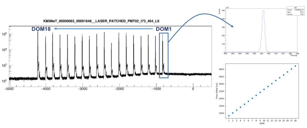
One of the main goal of the DU tests at process 3 is the inter-DOM calibration in a dark box, that consists of the time delay measurement between DOMs. The DOMs are separated by a fiber length of about 36 m that corresponds to a time delay of about 180 ns. In order to reach the required synchronization at sub-nanosecond level, the time offsets between the master clock onshore and the local clocks distributed to the DOMs must be well measured. In addition, since the DOM readout electronic board is segmented into two hemispheres, the two paths can introduce a possible time difference. The DU time calibration can be performed in the dark box by means of a laser source and a light distribution system that provides laser pulses at s.p.e. (single photoelectron) level directly and simultaneously to two reference PMTs of all the DOMs. Additionally, these double-time measurements for each DOM allow an essential redundancy in case of an issue of one PMT or readout electronics. The measurements of the time calibration constants of each DOM, as shown in Figure 2, are essential during the deployment and the proper sea operation.
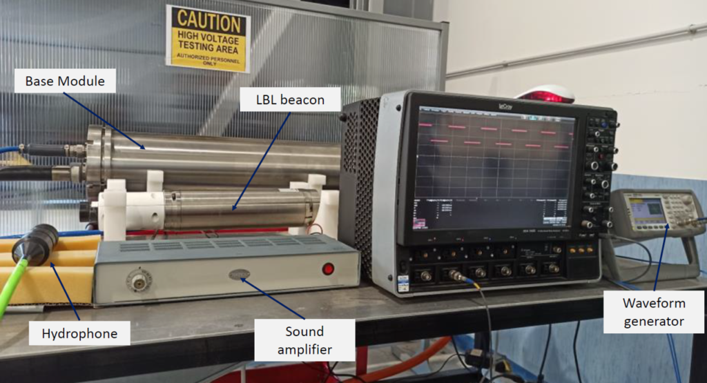
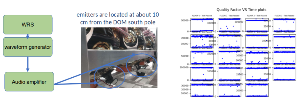
During the DU calibration we fully check the functionality of all the acoustic devices used for the positioning system. To validate the acoustic devices in each string, several careful checks are performed. Firstly, communication tests and power consumption measurements are done. Then, the acoustic receiver functionality of the hydrophone and DARs (Digital Acoustic Receivers) can be tested. For this purpose, the setup, as shown in Figure 3, consists of a waveform generator, a sound amplifier-and-splitter (1/20) coupled with acoustic piezoelectric emitters (positioned at about 10 cm from the DOM south pole, near the piezo receiver). A sinusoidal wave emission at 30 kHz frequency and an amplitude of 2 Vpp is set. The acoustic emission is synchronised with the master clock system of data acquisition. The acoustic data frames, thanks to a dedicated data filter on the online processing server, are quickly available on the DB and the correct detection of acoustic signals is checked through an analysis of the ToA (Time of Arrival) of the emitters’ signals and their synchronicity with respect to the DU master clock. The results are shown in Figure 4.
A crosscheck of the inter-DOM time calibration performed in the dark box can be carried out in-situ after the DU deployment through the Light Emission Diode beacon (Nanobeacon, NB) installed in the upper part of each DOM. A short light pulse at a fixed wavelength of 470 nm with the possibility to configure the intensity and frequency of flashing is controlled by the CLB logic. Measurement of time differences between pairs of DOMs allows calibration of the surrounding DOMs with respect to the one emitting light. The NB functionality tests are performed in the dark box by checking the hits in the PMTs closest to the emitting NB. Dedicated runs are taken with a bias voltage scan for each DOM NB.
DUs calibrated at the CAPACITY LAB: 30
06/02/2025